Repairing the internal switch on
the Fiat Spider
You may click on the pictures
for larger versions
Additional Pictures
of the Ignition Switch: (Brad Artigue)
Expalnation of switch positions / wiring colors Here
Photo of rear of switch with color information Here
Pictures will open
in new window
| |
Tools and Parts List |
|
A
Fiat with a messed up ignition switch.
Soldering gun
1/8" drill bit
5/64" drill bit
Loctite |
Qty
4 2 x 20mm machine screws with nuts. (Were available at
my local Sears hardware). Other option is 5/64" x 3/4". |
Small
flat bladed screwdriver Tweezers
Needle nose pliers
Optional: Dremel tool with wire brush attachment. |
Procedure
I. Remove
the ignition switch. Believe it or not this will take you less than
5 minutes. The procedure is described nicely in the factory manual
but briefly ...
- Unplug both
connectors connecting the switch to the wiring harness
- Remove the
lower portion of the plastic steering column surround. If you
don't do it now, you'll have to later since the column lock will
catch on it as
you try to remove the switch from the housing.
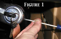
- Insert key
into the ignition
- Turn key until
it aligns with the arrow stamped into the face of the switch.
This will allow the column lock to retract. It also sets things
up internally
within the switch so that you can push in the mechanism that
holds the switch
in the housing. See Figure 1.
- Remove the
boot at the back of the switch. Mine was already cut lengthwise
and held in place with wire ties so I just removed it. If it
is still intact you may
be able to simply slide it back.
- Remove the
2 set screws holding the switch to the housing.
- At about the
03:00 position on the switch/housing assembly there is a slot.
Take a small thin flat bladed screwdriver and push in through
the slot. While
pushing in with the screwdriver, push the switch from behind.
It should slide
out easily. If it does not, rotate the key ever so slightly in
one direction or the
other and try again. See Figure 1.
- The switch
may get 'stuck' after about an inch as you slide it out. Don't
panic,
it's probably the column lock catching on the metal of the steering
column.
You can remove the screwdriver from the slot now and use it to
gently pry the
column lock back the 1/8" that you need.
II. Remove
the electricals from the back of the switch.
- Lay the switch
on your workbench and take a look at it from behind. There
is a large internal circlip that is holding the electrical contact
assembly to the
back of the switch.
- Remove the
circlip nothing complicated about this.
- Remove the
contact assembly from the back of the switch by giving a gentle
tug on the pigtail. Set the main part of the switch aside. You're
done with that.
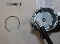
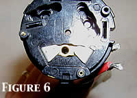
- Picture FIGURE
3 shows the circlip laying beside the switch assembly after
the contact assembly has been removed.
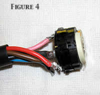
- Picture FIGURE
4 shows the contact assembly.
- Now, before
you go any further, take some sort of marker, paint, whatever
and
mark the 3 pieces that comprise the contact assembly relative
to each other.
That way when you put it back together all you have to do is
align the marks.
You'll see in picture FIGURE 4 that I used some yellow paint.
III. Un-solder
the connections
- First off,
MAKE A DIAGRAM OF WHERE ALL OF THE
WIRES ARE CONNECTED!
- Now it's time
to remove the 'pigtail' wiring from the spade terminals on the
back
of the contact assembly. This is a critical operation. A light-duty
hobbyist's
soldering 'iron' will not work very well. I suggest a Weller
or similar medium-
heavy duty soldering gun.
- The most critical
part of this operation is that you get as much of the solder
off
of the spade terminals as possible. Your success in this area
will pay off later as
you try to remove the spade terminals from the assembly.
IV. Disassemble
contact assembly Now the FUN BEGINS!
- Ever so carefully
take a drill with a 1/8" bit and begin drilling out the
crimped
part of the rivet at the center of the white plastic rotating
disk. Be very careful
not to go too deep. You're only trying to cut the crimp off with
the drill bit
tip so that you can press the rivet out later.
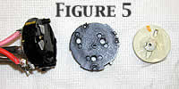
- Once the rivet
is cut, set the assembly so that it is resting on the spade terminals
and take a small screwdriver and carefully pry the disk off of
the main assembly.
In FIGURE 5 you can see the disk and its washer removed.
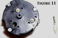
- Behind the
disk are 3 spring loaded pins. The ramps on the back side of
the
disc act on these pins to 'make' or 'break' the electrical contacts.
Carefully lift
these pins out with a pair of tweezers. Refer to FIGURE 11. Note:
This
picture was taken at the time of reassembly, that is why you
see screws
instead of rivets holding the assembly together.
- Now take your
drill bit and cut out the rivets holding the 2 black disks together
in the same way that you did in step 4.1
- Once the rivets
are removed, working around the perimeter, carefully pry the
2 black disks apart a little at a time.
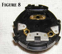
- Once the disks
are separated you will see something similar to FIGURE 8.
Note that the top set of contacts in this picture are already
partially disassembled.
- Now, let's
see how good you were at removing all of the solder from the
spade terminals on the back of the assembly.
- From behind,
using your tool of choice, push a spade terminal back thru the
assembly. They are tight, but they WILL slide out. Be VERY careful
to maintain
the 90 degree bend of the contact assembly (opposite end from
the spade terminal.
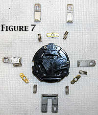
- Now remove
the brass contact assembly and the 2 small springs underneath.
- Repeat this
process for all spade terminals.
When you're all done, you should have something that looks like
FIGURE 7.
- Now, break
out the Dremel tool and clean up all of the contact points with
a
wire brush attachment if you have one. Otherwise use some other
form of very
fine abrasive. Be VERY careful to only clean up the burned areas.
Remove as
little material as possible.
- Once everything
is cleaned up, remove the rivets from the assembly completely
(if you haven't done so already). You are going to replace them
with screws.
V. Reassemble
the contact assembly
- Using a 5/64"
drill bit enlarge the 3 holes around the perimeter of the 2 black
contact
assembly disks. You are doing this because the screws that you
are going to put
back in there are slightly larger than the original rivets. There
is NO NEED to enlarge
the center hole that secures the white plastic rotating disk;
it is large enough already.
- Now carefully
reassemble the contact assembly. This will require PATIENCE J
It is easiest to work on one contact set at a time.
- Drop the 2
little springs that the brass contact rides on into place.
- Lay the brass
contact on top with the contact points pointing up towards you
(away from the springs).
- Now, carefully
push the spade terminals for that contact back through the black
plastic
disk and push them all the way down until they make contact with
the brass piece.
FIGURE 8 shows the contact reassembly partially complete. Be
careful that the
springs under the brass contacts don't fall over.
- Once you have
all of the springs, contacts and spade terminals back in place,
use your alignment marks to put the 2 black disks back together.
- Before completing
the next steps please take note that nuts that you will use
will interfere with the internal circlip when you try to reinstall
the contact assembly
into the main switch. This is shown in FIGURE 12. My solution
was to cut the
circlip in a couple of pieces and use the nuts as 'stop' points
for the circlip. This is
not my preferred solution but it worked. If I had to do it again
I would grind one
side of the nut flat BEFORE I reassembled. I would grind it almost
to the point of
cutting into the threaded hole at the center of the nut. Then
the ring would be able
to slip past the nut and into its groove. If this works, shoot
me an email and I'll update
this document.
- Hold the 2
black disks together and insert a 2x20mm machine screw (or 5/64"
x 34")
and a nut (with Loctite) in each perimeter hole to hold everything
together. Make
sure to orient the screws as shown in FIGURE 10.
- Now trim the
excess thread from the rear of the assembly using a pair of wire
cutters.
- Next, put
the spring loaded pins back in place
- Next place
the white plastic rotating disk back into position and slip a
screw through it.
Orient the screw as shown Figure 12. On the spade terminal side
of the contact put a
drop of Loctite on the screw and install the nut.
- Solder the
wires back onto the contact assembly.
Place the contact assembly back into the ignition switch, taking
note that it will only fit
in 1 direction.
- Reinstall
the internal circlip
- Reinstall
the ignition switch in the car and YOU'RE done!
|


|